Introduction
The 600VDC-30A three-phase inverter uses the IPM module FSBB30CH60C from onsemi as its core part. The inverter is designed to convert DC to AC power only. There is neither necessary voltage sensing nor current sensing, as these two parts are designed as separate boards. The only protection mechanism on this board is a fault signal generated by FSBB30CH60C. Without current/voltage measurement, the board must be tested carefully to avoid blowing up.
Board description
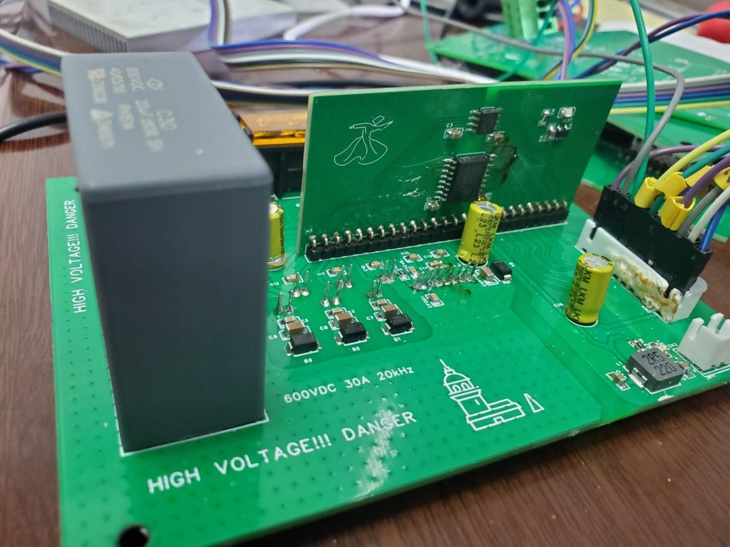
The inverter board consists of two parts and offers galvanic isolation.
The hardware project is provided in the link: 3ph-AC-DC-Cihangir
The motherboard is where the IPM module is mounted. The boost-strap circuit of the high side is also on the motherboard. It connects to the MCU board via an xh-2.54 10 pin socket. The power sockets for both galvanically isolated part and the user (MCU) part are imported via an xh-2.54 2 pin socket. These xh sockets provide the best flexibility when using the cable having the xh head. Nevertheless, the Dupont line with glue fixing can also work reliably.
A 26 pin 2.54mm pin is used to connect the daughter board with the motherboard. The power supply of the daughter board is transferred from the 26-pin socket. Two isolating chips are used to transmit the PWM signal and fault signal. The short current sensing is currently included in the 26-pin signals, but this design will be removed in the future version because the short current sensing should be processed locally to obtain timely protection. There is no need to feed this signal to the MCU side.
It is noted that the board does not have any prevention of shoot-through if false PWM is generated!!! So it is critical that the MCU provides the pairs of PWM signals with enough dead-time setting.
One important reminder here is that two popular dev-boards, the launchpad from TI and the nucleo from ST, have different PWM pin arrangements!!! The launchpad from TI arranges the 6 PWM pulses as 1H,1L,2H,2L,3H,3L while the nucleo from ST arranges the 6 PWM pulses as 1H,2H,3H,1L,2L,3L. The inverter board uses the ST convention. Care must be taken to avoid mixing the TI convention and ST convention.
Without proper short circuit current sensing, the board cannot withstand any short-circuited load. So double-check the load connection before firing the pulse.
Soldering
The first step is to solder the daughter board completely.
Then, soldering the surface mount devices on the motherboard using the heat gun. Remember not to use a heat gun to solder the socket because the hot air might destroy the xh socket. The through-hole devices can be soldered by the iron.
It is recommended to solder a 26-pin female socket on the motherboard, and solder a 26-pin 90-degree bent male socket on the daughter board. This will make the assembly of the boards more flexible.
The printed pictures on the daughter board and the mother board indicates the galvanic side. Make sure the daughter board is mounted correctly.
Test procedure
Wiring the MCU and the inverter board
The cable of PWM signals must be connected in ST convention to avoid a short-through event. It is recommended to put a small piece of ring notes through the lines, marking the number of PWMx.
Programming an open-loop duty-cycle output
In STM32 MCU boards, writing a simple program of synthesizing a 1.0 p.u 50Hz three-phase waveform. Such a waveform will cover all the possible duty cycle settings from 0.0 p.u to 1.0 p.u.
F4_openloop
Using an oscilloscope to check whether the waveform of three pairs of the complementary pulses
Using the normal triggering mode and single triggering mode of the oscilloscope, make sure that the PWM signals generated by the daughter board (the galvanically isolated one) are correct.
Testing in a 100W load setup
Our lab has prepared a three-phase R load, together with a 3mH L filter. When the inverter works at 10-20KHz switching frequency, the current waveform will be smooth, with only a small distortion caused by the dead time. The DC power source is recommended to be provided by a commercial DC source with over-current protection, which could be useful to avoid excessive current feeding in some unexpected fault during the test and save the IPM from disaster.